

A&N Engineering Services Limited follow the industry standard ISO 2768-1.
As a general rule, where no tolerance is indicated we try to work between 0.5mm and 0.3mm as standard, unless customer drawing dictates tighter or looser dimensions.
International standard and its implementation make designing and manufacturing more accessible and convenient.
Partnerships between manufacturing companies are also more seamless.
ISO 2768 comes in two parts — ISO 2768-1 and ISO 2768-2.
These parts define mechanical precision levels to simplify technical drawings.
-
Part 1 – General Tolerances for linear and angular dimensions.
The precision here is defined as fine, medium, coarse, and very coarse. -
Part 2 – Geometrical tolerances for features. Precision levels or tolerance classes here are H, K, and L.
ISO 2768 Part 1: Linear and Angular Dimensions
The ISO 2768-1 intends to simplify drawing indications.
This part specifics the general tolerances in four different classes, namely:
-
f – Fine
-
m – Medium
-
c – Coarse
-
v – Very Coarse
ISO 2768 part one applies for linear and angular dimensions.
These dimensions include;
internal sizes, external sizes, radii, external radii, diameters, chamfer heights, and step sizes.
They are dimensions of components produced using metal removal.
Table 1 – Linear Dimensions
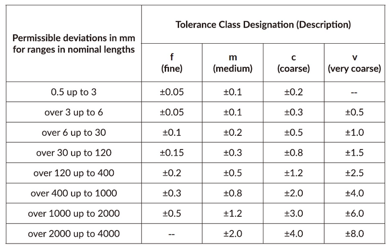
Designers shall indicate nominal sizes lesser than 0.5 mm adjacent to the appropriate size.
Table 2 – External Radii and Chamfer Heights
Similarly, Table 2 indicates tolerance standards for external radii and chamfers.
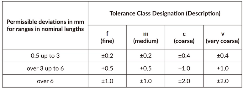
Designers shall indicate nominal sizes lesser than 0.5 mm adjacent to the appropriate size.
Table 3 – Angular Dimensions
This table defines tolerance standards for angular dimensions.
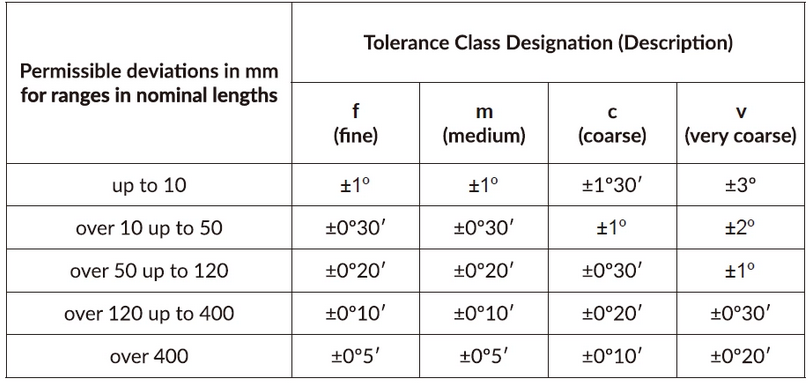
The tolerances in this table are in minutes and degrees, as you would expect for angular dimensions.
ISO 2768 Part 2: Geometrical Tolerances for Features
This part includes general geometrical tolerances of straightness and flatness. It also includes circularity and cylindricity. ISO 2768-2 simplifies draws, fixing general tolerances in three classes — H, K, and L.
It also mainly applies to parts created by material removal.
There are four tables here with respect to general geometric tolerances of dimensions and further information.
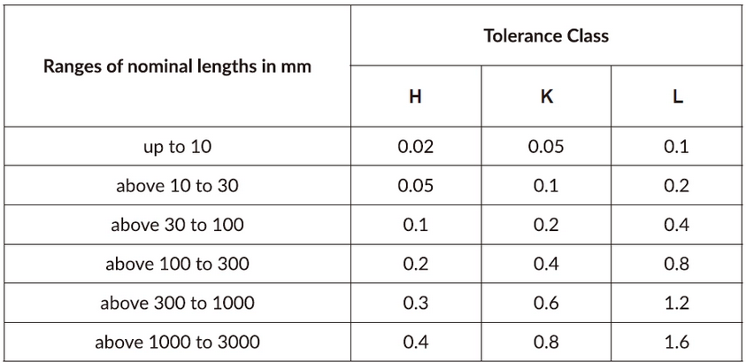
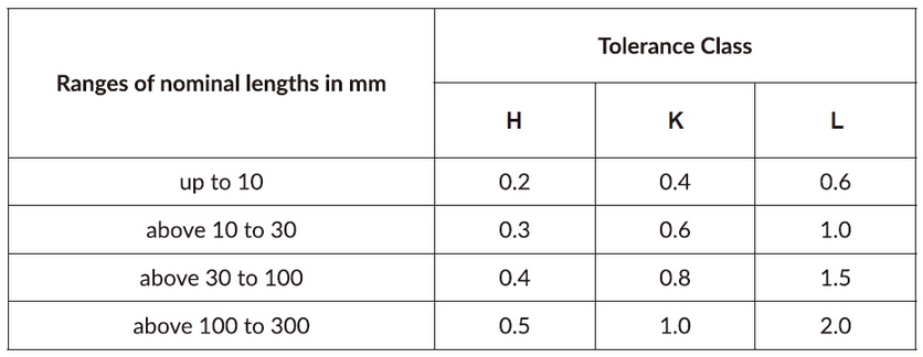
Table 4 – General Tolerances on Straightness and Flatness
This table defines straightness and flatness ranges. Let’s take a compressor base as an example.
First, it is essential to consider the contact surface between the engine and the base and the contact surface between the base and compressor.
This will help you specify their flatness ranges in the drawing.
Straightness tolerances will control the level at which a surface varies from a specified line.
They also help control the number of twists or bends allowed.
Table 5 – General Tolerances on Perpendicularity
Perpendicularity comes in distance units like inches or millimeters.
Its general tolerance standards are summarised below.
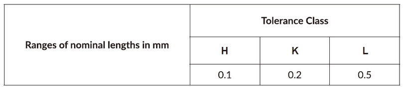
Table 6 – General Tolerances on Symmetry
This table shows general geometrical characteristics for Symmetry with permissible deviations for some features which may be uniform across a plane.
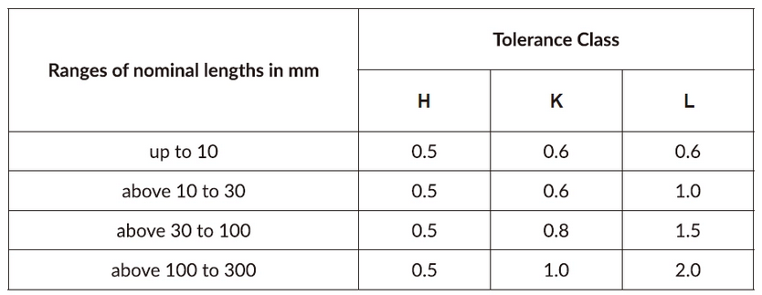
Table 7 – General Tolerances on Circular Run-Out
Table 7, which happens to be the final table of the ISO 2768, corresponds to Run-out.
This is the total permissible variation of a surface when you rotate the part around an axis.
Why is ISO 2768 Important?
ISO 2768, as an international tolerance standard, is essential for simplifying drawing specifications used in geometrical tolerances.
It also puts you on an equal page with designers and manufacturers worldwide to prevent manufacturing misunderstandings.